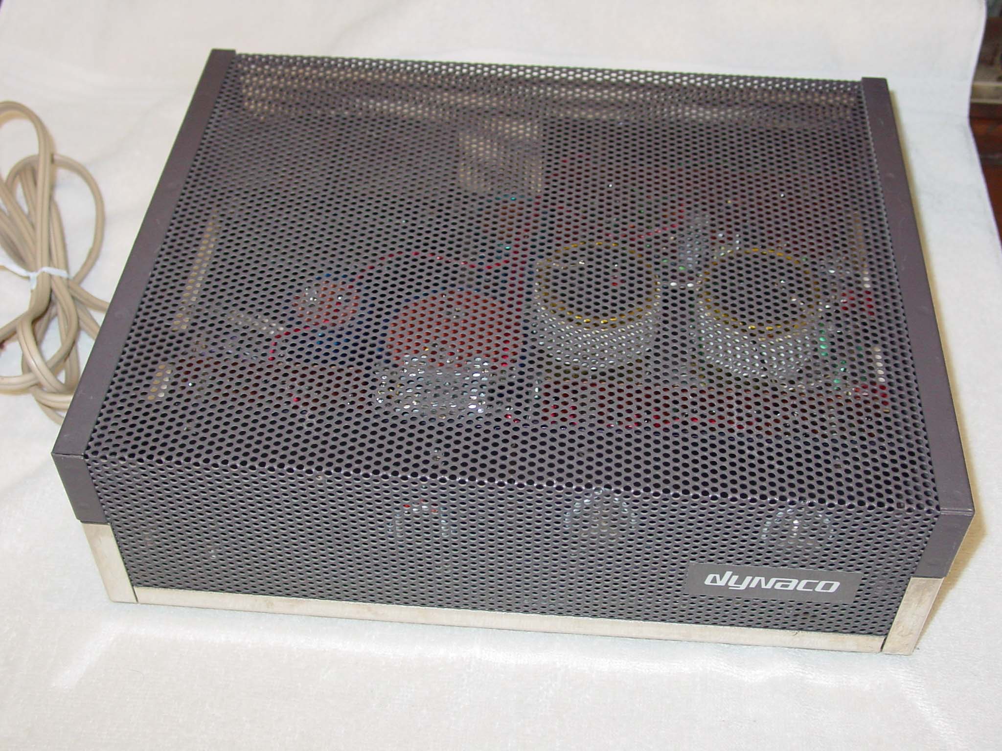
This page contains everything I know about the Dynaco Stereo 120 power amplifier. This was Dyna’s first transistor amplifier, introduced in 1966 and sold for more than 10 years. The design was minimalist – only 6 transistors were used per channel. The unit operated in a class A-B mode (like many tube amplifiers) and used a whopping big output capacitor to decouple the DC offset of the amp (like tube amps use an output transformer).
Over those years, many small circuit changes were introduced to improve the stability and reliability of the amp. These amplifier improvements/changes fall into 2 categories: 1) ruggedness of components and 2) stability of design.
POWER SUPPLY
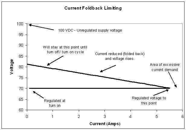
The original power supply was unique, supplying regulated 70 VDC @ 3 amps to the unit. To avoid fuses, circuit breakers etc. the power supply utilized current foldback limiting. It was designed to supply regulated power to both amplifier channels, but to shut down if a channel was shorted and drew too much current. The power supply was meant to operate in the normal ‘regulated’ mode and supply current at a regulated voltage up to a certain demand. If the amplifier stages were demanding more current, something was probably wrong (shorted outputs). Under excessive current demand, the current supply was reduced (‘folded back’) and the voltage rose. The amp stayed in this condition until it was turned off and turned back on. Of course, if there was a failure condition, like shorted outputs, the power supply went right back into current limiting.
This was a very clever design, but suffered from problems of reliability. If the power supply failed in the unregulated mode, and applied 100VDC to the output stages, these often failed in short order. Proper power supply repair required matching components. These supplies were often repaired poorly and poor repair led to repeated failure of the entire unit.
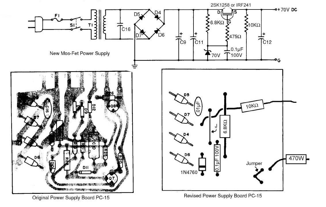
The MOSFET regulated power supply shown below uses a simple Zener diode and a Power MOSFET to give good regulation at 70 Volts at any current. The simple rugged design allows the uses of fuses in the power supply, a 3 amp fuse for each channel. The supply regulates better, runs cooler, and protects the amplifier better. All the original power supply caps are used in this modification.
Here’s an excellent description of the Dynaco 120 in general, and the power supply in particular
Power supply upgrade and TIP mods
.
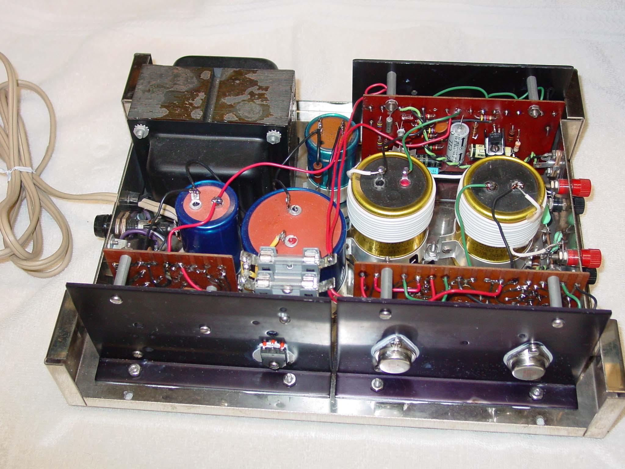
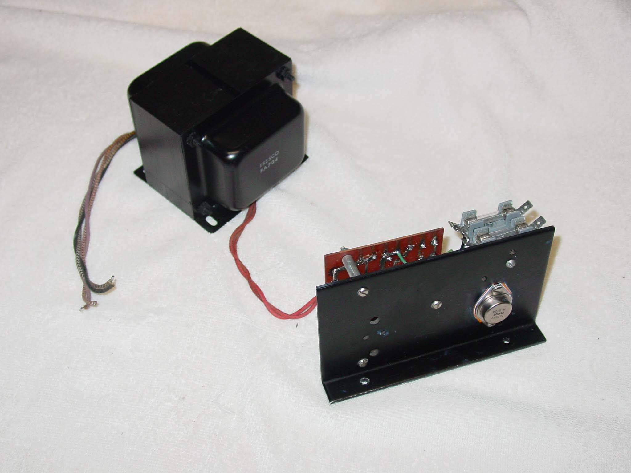
The ST120 transformer with the MOSFET power supply modification
TIP Modification
For component ruggedness, most of the active devices were updated in what is generally referred to as the TIP modification. This is named after the TIP series of power transistors which are used to replace some of the original DYNA devices. ALL the transistors are replaced in the TIP modification. The output transistors (originally the common 2N3055 type) are replaced with the higher gain, higher voltage 2N3772.
FROM THE DYNA SERVICE BULLETIN:
Q1 replace 40233 (100-250 beta) with BC108A (130-180 beta)
Q2 replace 2N3053 (100-200 beta) with 2N5320 (160-260 beta)
Q3 replace 2N3053 with TIP31C
Q4 replace 2N4037 with TIP32C
Q5, Q6 replace 2N3055 (17-25 beta) with 2N3772 (60-90 beta @ 1A)
D1 replace with 1N4733
D2,3 replace with 1N4004
C1 replace with 5 µF 10V tantalum
Add C13 68 pF from Q2C to Q2B, both channels
Add C14 0.01 µF from Q3C to GND, both channels
Add C15 27 pF from Q2C to Q1E, both channels
Add C16 .01 µF across xfmr secondary at rectifier bridge on PC-15
Replace C6 (30 µF, NP) with .47 µF mylar
Add 3.3 Ohm ½ watt emitter resistor to Q4, both channels
Add 1 kOhm 1.2 watt resistor across the red/black output jacks
For circuit stability, several capacitors and resistors were added to stabilize the circuit configuration. These changes kept the amplifier stable as the components aged. Whenever I work on equipment that is over 20 years old, I always replace the electrolytic capacitors. This takes just a few dollars and a few minutes per channel on the Stereo 120. There are several large, high voltage capacitors in the ST-120, three in the power supply, and one each in each channel. I’ve never seen these fail, but if they do, replacements will be expensive and physically smaller.
There are two 300 ohm 7 watt resistors on each amplifier PC board. These resistors dissipate 5 watts of power and run hot all the time, and have likely discolored the circuit board. I’ve seen several of these burn out. They can be replaced with 330 ohm 10 watt units. 330 ohm is 10% above the original resistance, but this value is MUCH easier to find.

I was tired of the neon pilot light built into the switch, so I used one of the new super bright LEDs. I put the LED with a 10 kOhm 2 watt current linmiting resistor across a power supply cap with 100 VDC on it.
Transistor substitution
|
Original Type
|
‘TIP Mod’
|
Acceptable alternates
|
|
| Q1 | 40233 | BC108A | NTE123A |
| Q2 | 2N3053 | 2N5320 | |
| Q3 | 2N3053/2N5320/2N3440 | TIP31C | |
| Q4 | 2N5322/2N4037/2N5416 | TIP32C | |
| Q5,6 | 2N3055/2N5630 | 2N3772 | |
Dynaco’s original product description:
The Dynaco Stereo 120 is an all silicon transistor basic power amplifier for use with separate preamplifiers such as the Dynaco PAT-4 or PAT-5, or for use with tape recorders or tuners such as the FM-5 or AF-6, which have their own volume controls. The Stereo 120 contains two 60 watt amplifiers on one chassis with a common power supply.
Although the Stereo 120 is a solid state device containing transistors and similar semi-conductors, it has been designed to be used under normal conditions without special safety precautions, just as if it were a high grade tube amplifier. Thus it can be connected to source and speaker components and used with confidence in all conventional arrangements. There are no circuit breakers, speaker fuses, or other resettable devices to impede the use of the Stereo 120 under any reasonable conditions of use or abuse. This is achieved by using novel circuits (on which patents are pending) which automatically and instantly protect the amplifier.
The components of the Stereo 120 are of the highest quality to protect against failure, both now and for many years in the future. All parts are used conservatively with close tolerances to assure continued proper operation, and etched circuit modules have been pretested under actual use conditions to ensure that every unit, after assembly, will meet the specifications normally associated only with laboratory prototypes.
The specifications of the Stereo 120 speak for themselves. The distortion and noise, up to levels well beyond those required to drive any conventional amplifier, are comparable to the finest tube designs while the high power distortion remains inaudible. Specifications do not reveal all the facets of superior audio performance, however. In use with varying program material, the Stereo 120 achieves its design goals of sonic ease and naturalness always sought but rarely achieved in solid state designs. There is remarkable clarity and an impression of direct contact with the original without the extra brightness or stridency which, unfortunately, is sometimes attributed to high fidelity sound, but rather there is an impression of limitless range and effortless handling of the highest power peaks.
Specifications:
Frequency Response: 5 Hz to 100 KHz ±0.5 dB.
Power Output Rating: 60 watts average continuous power per channel into 8 ohms at any frequency between 25 Hz and 15 KHz at less than 0.5% total harmonic distortion. Distortion reduces at lower power levels. This is in accordance with F.T.C rating requirements, including preconditioning.
Intermodulation Distortion: Less than 0.5% at any power level up to 60 watts per channel into 8 ohms with any combination of test frequencies. Distortion reduces at lower power levels.
Noise: 95 dB below rated output, unweighted with shorted input; 100 dB down by IHF standards.
Damping Factor: Greater than 40 from 20 Hz to 20 KHz.
Separation: more than 70 dB from 20 Hz to 20 KHz.
Input: 100,000 ohms; 1.5 volts for 60 watts output.
Semiconductor Complement: 15 transistors; 15 diodes.
Size: 13″ by 10-1/2″ by 4″.
Weight: 20 lbs.
Maximum Power Consumption: 400 watts.
Designed by:
Ed Laurent (power supply by Sid Lidz)
Year Introduced:
1966
Price:
$209.00 kit
$289.00 assembled